Categories
- Conventional fire alarm systems
- Wireless Fire Alarm System
- LPCB addressable fire alarm
- Addressable fire alarm system
- Gas detection alarm system
- Electrical Fire Monitoring
- Fire Alarm Fire Extinguishing
- Fire Alarm gas fire-extinguish
- Commercial Burglar Alarm System
- Security Service Equipment
- Commercial security solutions
- Industry Security Equipment
Manufacturer Info
Languages
Important Links


Fire alarm and gas fire-extinguishing control panel
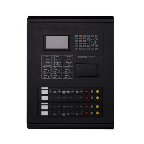
TC5105 fire alarm and gas fire-extinguish
Product Description
Gas fire-extinguishing system is mainly used in environments that are not suitable for setting water fire extinguishing system and other fire extinguishing systems, such as computer room, important library archives, mobile communication base station (room), UPS room, battery room, general diesel generator room, etc.
* Color menu display
* Max 4 fire protection zones and 1 Fire Alarm loop
* Max 6 direct control points
* Networking function
* Built-in printer
* Wall-mounted structure ,compact and exquisite
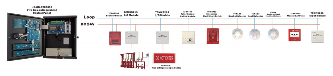
* Connection with field devices through loop control
* The system is a combination of alarm, linkage and gas fire-extinguishing
* Devices can be connected include smoke detector, heat detector, flame detector, MCP, emergency start/abort button, sounder strobe, gas spray indicator, auto/manual switch module and I/O module
Main power supply: AC220V(3A), Voltage range: +10%~-15%
Battery: DC24V (10A), 12V/12AH sealed acid battery *2
LCD screen: 4 inch color LCD screen, resolution:480*272
Capacity: 255~510 points /1~2 loops /2~4 zones
Operating environment: Temperature: 0~+40°C, relative humidity<=95% non-condensing
Dimension: 385mm*134mm*510mm
Communication interface: RS485, CAN, USB
L, N, PE: AC 220V terminals and AC grounding terminals. L+, L-: non polarized alarm loop signal bus system terminals. Qn+, Qn-: non-polarized gas loop signal bus system interface, n: gas zone, No.1~4.NO, CM, NC: fire alarm volt-free output interface (NO: volt-free open junction, CM: volt-free sharing junction, NC: volt-free closed junction). SG+, SG-: sounder strobe control output terminals (volt control point, active output DC24V, output DC24V stopped after manually stopped or reset).
A2, B2: RS485 terminals connecting figure display in fire protection control room, A2 for A point of485, B2 for B point of485.
Al, BI: RS485 terminals, Al for A point of485, BI for B point of 485 (optional). Qn, Gn, Hn: direct control interface of threc-wire system, n for loop No. for three-wire system,No. 1-6. CH, CL: polarized Can bus system of control panel networking.
JP2: pin set at the peripheral networking terminal on loop mainboard. Short cut piece jumps to ON when the panel is connected to peripheral network terminal,24V, GND: linkage power output terminals. Encode corresponding detectors and modules of gas fire-extinguishing.