Categories
- Conventional fire alarm systems
- Wireless Fire Alarm System
- LPCB addressable fire alarm
- Addressable fire alarm system
- Gas detection alarm system
- Electrical Fire Monitoring
- Fire Alarm Fire Extinguishing
- Fire Alarm gas fire-extinguish
- Commercial Burglar Alarm System
- Security Service Equipment
- Commercial security solutions
- Industry Security Equipment
Bestsellers
- Break beam solar power wireless...
- High Sensibility smoke and heat...
- Horn strobe flash and sounder fire...
- Audio visual alarm conventional...
- Conventional manual call point ...
- PIR detector solar power wireless...
- Solar Power wireless beam...
- Conventional fire alarm sounder...
- Wireless infrared beam security...
Important Links
linkage fire alarm system parts
Fire alarm controller and fire linkage controller are integrated products, called the linked fire alarm controller.
The main components of the linked fire alarm controller include motherboard, display board, bus linkage control panel, multi-line linkage control panel, network interface component, power supply, loop board and so on.
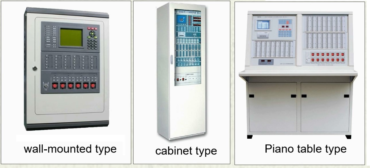
The power supply of the controller is not only provided to the controller itself and the demand of the loop, but also can supply power for part of the linkage equipment.
For the case of large power load, you can add a power box on the controller, and you can also set separate fire power supply on the site to supply power for the linkage control module and the controlled device.
Loop board has the form of single loop and two loops, can be connected to one or two bus loop.
The bus loop is the alarm linkage bus circuit. Each loop supports a certain number of address points and can equip a certain number of coding devices. Each device occupies an address point.
All kinds of detectors, manual alarm buttons, modules, and acousto-optic alarms with address coding can be connected to the bus loop in parallel.
For the non-coded detector or switch contact signal without address code, it can be connected to the bus loop by loading the address code through the input module or relay module.
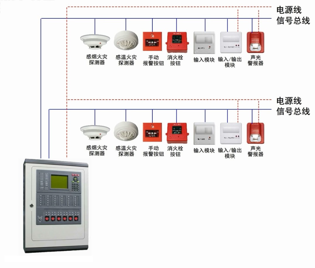
For example, the maximum address point of each loop of the controller is 252. Theoretically, each loop can equip up to 252 address coding devices, corresponding to 252 address points respectively.
According to the specification requirements, in fact, the total number of devices connected by each bus loop should not exceed 200 points, and the allowance should not be less than 10% of the rated capacity.
Different manufacturers or different types of fire alarm controller can load different number of loop board, each loop address point is also different.
Loop board is a modular component, by increasing or decreasing the number of loop board can adjust the controller point.
 Security Alarms
